

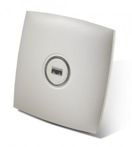


Cisco Aironet ANT2465
The antenna operates in the 2.4-GHz frequency range and is designed for use in both indoor and outdoor environments.
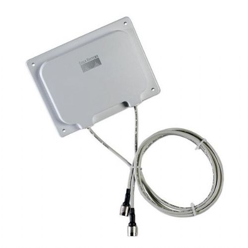
This document outlines the specifications, describes the AIR-ANT2465P-R 6-dBi patch antenna, and provides instructions for mounting it. The antenna operates in the 2.4-GHz frequency range and is designed for use in both indoor and outdoor environments.
|
Antenna type |
Diversity patch |
|
Operating frequency range |
2400 - 2484 MHz |
|
Nominal input impedance |
50W |
|
2:1 VSWR bandwidth |
2400 - 2484 MHz |
|
Peak gain |
6.5 dBi |
|
Polarization |
Linear, vertical |
|
E-plane 3-dB beamwidth |
65° |
|
H-plane 3-dB beamwidth |
75° |
|
Front-to-back ratio |
15 dB |
|
Cross-pol discrimination |
15 dB |
|
Cable length and type |
36 in. (91.4 cm) |
|
Connector type |
RP-TNC |
|
Length |
4.4 in. (11.1 cm) |
|
Width |
6.6 in. (16.7 cm) |
|
Height |
1 in. (2.5 cm) |
|
Operating temperature range |
-22°F to 158°F (-30°C to 70°C) |
|
Storage temperature range |
-40°F to 185°F (-40°C - 85°C) |
|
Environment |
Indoor/outdoor |
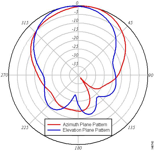
Left Antenna Azimuth and Elevation Pattern
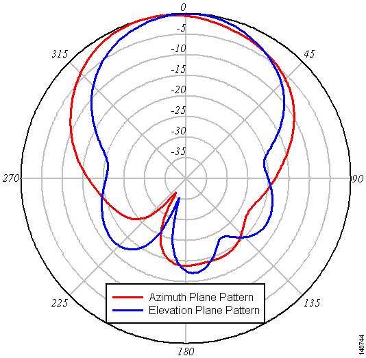
Right Antenna Azimuth and Elevation Pattern
System Requirements
This antenna is designed for use with Cisco Aironet access points and bridges but can be used with any 2.4-GHz Cisco Aironet radio device that utilizes an RP-TNC connector.
Safety Precautions
Translated versions of the following safety warnings are provided in the Safety Warnings for Cisco Aironet Antennas, which is available at http://www.cisco.com.
Each year hundreds of people are killed or injured when attempting to install an antenna. In many of these cases, the victim was aware of the danger of electrocution, but did not take adequate steps to avoid the hazard.
For your safety, and to help you achieve a good installation, please read and follow these safety precautions. They may save your life!
1. ![]() If you are installing an antenna for the first time, for your own safety as well as others, seek professional assistance. Your Cisco sales representative can explain which mounting method to use for the size and type antenna you are about to install.
If you are installing an antenna for the first time, for your own safety as well as others, seek professional assistance. Your Cisco sales representative can explain which mounting method to use for the size and type antenna you are about to install.
2. ![]() Select your installation site with safety, as well as performance in mind. Remember: electric power lines and phone lines look alike. For your safety, assume that any overhead line can kill you.
Select your installation site with safety, as well as performance in mind. Remember: electric power lines and phone lines look alike. For your safety, assume that any overhead line can kill you.
3. ![]() Call your electric power company. Tell them your plans and ask them to come look at your proposed installation. This is a small inconvenience considering your life is at stake.
Call your electric power company. Tell them your plans and ask them to come look at your proposed installation. This is a small inconvenience considering your life is at stake.
4. ![]() Plan your installation carefully and completely before you begin. Successful raising of a mast or tower is largely a matter of coordination. Each person should be assigned to a specific task, and should know what to do and when to do it. One person should be in charge of the operation to issue instructions and watch for signs of trouble.
Plan your installation carefully and completely before you begin. Successful raising of a mast or tower is largely a matter of coordination. Each person should be assigned to a specific task, and should know what to do and when to do it. One person should be in charge of the operation to issue instructions and watch for signs of trouble.
5. ![]() When installing your antenna, remember:
When installing your antenna, remember:
- Do not use a metal ladder.
- Do not work on a wet or windy day.
- Do dress properly—shoes with rubber soles and heels, rubber gloves, long sleeved shirt or jacket.
6. ![]() If the assembly starts to drop, get away from it and let it fall. Remember, the antenna, mast, cable, and metal guy wires are all excellent conductors of electrical current. Even the slightest touch of any of these parts to a power line complete an electrical path through the antenna and the installer: you!
If the assembly starts to drop, get away from it and let it fall. Remember, the antenna, mast, cable, and metal guy wires are all excellent conductors of electrical current. Even the slightest touch of any of these parts to a power line complete an electrical path through the antenna and the installer: you!
7. ![]() If any part of the antenna system should come in contact with a power line, don`t touch it or try to remove it yourself. Call your local power company. They will remove it safely.
If any part of the antenna system should come in contact with a power line, don`t touch it or try to remove it yourself. Call your local power company. They will remove it safely.
8. ![]() If an accident should occur with the power lines call for qualified emergency help immediately.
If an accident should occur with the power lines call for qualified emergency help immediately.
Installation Guidelines
Because the antenna transmits and receives radio signals, they are susceptible to RF obstructions and common sources of interference that can reduce throughput and range of the device to which they are connected. Follow these guidelines to ensure the best possible performance:
•![]() Mount the antenna to utilize its propagation characteristics. One way to do this is to orient the antenna vertically and mount it as high as possible.
Mount the antenna to utilize its propagation characteristics. One way to do this is to orient the antenna vertically and mount it as high as possible.
•![]() Keep the antenna away from metal obstructions such as heating and air-conditioning ducts, large ceiling trusses, building superstructures, and major power cabling runs. If necessary, use a rigid conduit to lower the antenna away from these obstructions.
Keep the antenna away from metal obstructions such as heating and air-conditioning ducts, large ceiling trusses, building superstructures, and major power cabling runs. If necessary, use a rigid conduit to lower the antenna away from these obstructions.
•![]() The density of the materials used in a building`s construction determines the number of walls the signal must pass through and still maintain adequate coverage. Consider the following before choosing the location to install your antenna:
The density of the materials used in a building`s construction determines the number of walls the signal must pass through and still maintain adequate coverage. Consider the following before choosing the location to install your antenna:
–![]() Paper and vinyl walls have very little affect on signal penetration.
Paper and vinyl walls have very little affect on signal penetration.
–![]() Solid and pre-cast concrete walls limit signal penetration to one or two walls without degrading coverage.
Solid and pre-cast concrete walls limit signal penetration to one or two walls without degrading coverage.
–![]() Concrete and wood block walls limit signal penetration to three or four walls.
Concrete and wood block walls limit signal penetration to three or four walls.
–![]() A signal can penetrate five or six walls constructed of drywall or wood.
A signal can penetrate five or six walls constructed of drywall or wood.
–![]() A thick metal wall causes signals to reflect off, causing poor penetration.
A thick metal wall causes signals to reflect off, causing poor penetration.
–![]() A chain link fence or wire mesh spaced between 1 and 1 1/2 in. (2.5 and 3.8 cm) acts as a harmonic reflector that blocks a 2.4-Ghz radio signal.
A chain link fence or wire mesh spaced between 1 and 1 1/2 in. (2.5 and 3.8 cm) acts as a harmonic reflector that blocks a 2.4-Ghz radio signal.
•![]() Install the antenna away from microwave ovens and 2-GHz cordless phones. These products can cause signal interference because they operate in the same frequency range as the device your antenna is connected to.
Install the antenna away from microwave ovens and 2-GHz cordless phones. These products can cause signal interference because they operate in the same frequency range as the device your antenna is connected to.
•![]() Install the antenna in a vertical orientation to maximize signal propagation.
Install the antenna in a vertical orientation to maximize signal propagation.
Site Selection
Before attempting to install your antenna, determine where you can best place the antenna for safety and performance.
Follow these steps to determine a safe distance from wires, power lines, and trees.
Step 1 ![]() Measure the height of your antenna.
Measure the height of your antenna.
Step 2 ![]() Add this length to the length of the structure on which you are mounting the antenna and then double this total for the minimum recommended safe distance.
Add this length to the length of the structure on which you are mounting the antenna and then double this total for the minimum recommended safe distance.
Caution ![]() If you are unable to maintain this safe distance, stop and get professional help.
If you are unable to maintain this safe distance, stop and get professional help.
Generally, the higher an antenna is above the ground, the better it performs. Good practice is to install your antenna about 5 to 10 ft (1.5 to 3 m) above the roof line and away from all power lines and obstructions. If possible, find a mounting place directly above your wireless device so that the lead-in cable can be as short as possible.
Installing the Antenna
You can install the antenna on any flat indoor or outdoor vertical surface. Hardware for mounting the antenna on drywall is provided. If you intend to install your antenna on another surface, you must provide the appropriate hardware.
Tools and Equipment Required
A mounting installation kit is shipped with the antenna and consists of the following hardware:
•![]() Four #8 x ¾ screws
Four #8 x ¾ screws
•![]() Four #8 plastic anchors
Four #8 plastic anchors
•![]() Four end caps
Four end caps
You need the following tools and equipment, which are not provided.
•![]() A Phillips screwdriver
A Phillips screwdriver
•![]() A drill
A drill
•![]() A #29 ((0.136-in (3.45 mm)) drill bit (For drywall installation, other surfaces may require a different size)
A #29 ((0.136-in (3.45 mm)) drill bit (For drywall installation, other surfaces may require a different size)
•![]() A pencil
A pencil
•![]() A small mallet or hammer
A small mallet or hammer
Mounting on a Vertical Surface
Follow these steps to mount your antenna on a vertical surface. This procedure describes mounting the antenna on a drywall surface. If you are mounting the antenna on any other type of surface, your procedure may vary slightly.
Step 1 ![]() Determine the location where you will mount the antenna.
Determine the location where you will mount the antenna.
Step 2 ![]() Use the antenna as a template to mark the locations of the four mounting holes.
Use the antenna as a template to mark the locations of the four mounting holes.
Step 3 ![]() Use a drill and #29 drill bit to drill four holes at the locations you marked in Step 2.
Use a drill and #29 drill bit to drill four holes at the locations you marked in Step 2.
Step 4 ![]() Start a plastic anchor into each hole.
Start a plastic anchor into each hole.
Step 5 ![]() Use a mallet or small hamer to seat the anchors into the wall.
Use a mallet or small hamer to seat the anchors into the wall.
Step 6 ![]() Align the antenna`s mounting holes with the anchors.
Align the antenna`s mounting holes with the anchors.
Step 7 ![]() Start a #8 x ¾ screw into each antenna mounting hole.
Start a #8 x ¾ screw into each antenna mounting hole.
Step 8 ![]() Use a Phillips screwdriver to secure the antenna to the wall. Do not overtighten.
Use a Phillips screwdriver to secure the antenna to the wall. Do not overtighten.
Step 9 ![]() Install the end caps into the antenna mounting holes.
Install the end caps into the antenna mounting holes.
Step 10 ![]() Remove the yellow outdoor installation warning label from the antenna radome.
Remove the yellow outdoor installation warning label from the antenna radome.
Outdoor Installations
You can mount this antenna outdoors. If you mount the antenna outdoors, you must provide the mounting hardware. For outdoor installations, Follow the instructions printed on the back of the antenna.
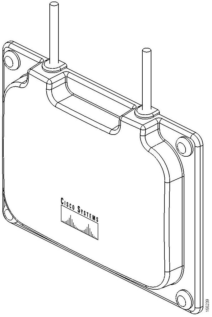
Caution ![]() An orientation arrow is printed on the back of the antenna that indicates the orientation for outdoor installations. You must install the antenna with the orientation arrow pointing down to prevent any water intrusion and to provide a drain for any moisture that may accumulate inside the antenna.
An orientation arrow is printed on the back of the antenna that indicates the orientation for outdoor installations. You must install the antenna with the orientation arrow pointing down to prevent any water intrusion and to provide a drain for any moisture that may accumulate inside the antenna.
Suggested Cable
Cisco recommends a high-quality, low-loss cable for use with the antenna.
Note ![]() Coaxial cable loses efficiency as the frequency increases, resulting in signal loss. The cable should be kept as short as possible because cable length also determines the amount of signal loss (the longer the run, the greater the loss).
Coaxial cable loses efficiency as the frequency increases, resulting in signal loss. The cable should be kept as short as possible because cable length also determines the amount of signal loss (the longer the run, the greater the loss).
The antenna terminates with a RP-TNC plug after a short, 3-ft (0.91-m) cable. The mating connector to the antenna is an appropriate RP-TNC jack. The connector on the opposite end will vary according to the type of equipment used.
After the cable is attached to the antenna, make sure that the connections are sealed (if outdoors) to prevent moisture and other weathering elements from affecting performance. Cisco recommends using a coax seal (such as CoaxSeal) for outdoor connections. Silicon sealant or electrical tape are not recommended for sealing outdoor connections.
Grounding the Antenna
Follow these steps to ground the antenna in accordance with national electrical code instructions.
Step 1 ![]() Use No. 10 AWG copper or No. 8 or larger copper-clad steel or bronze wire as a ground wire.
Use No. 10 AWG copper or No. 8 or larger copper-clad steel or bronze wire as a ground wire.
Step 2 ![]() Secure the ground wire to a static discharge unit (lightning arrestor, Cisco Aironet AIR-ACC245LA-R or equivalent) and then to a suitable building ground. If possible, route the ground wire from the discharge unit to the ground using stand-off insulators spaced from 4 ft (1.2 m) to 8 ft (2.4 m) apart.
Secure the ground wire to a static discharge unit (lightning arrestor, Cisco Aironet AIR-ACC245LA-R or equivalent) and then to a suitable building ground. If possible, route the ground wire from the discharge unit to the ground using stand-off insulators spaced from 4 ft (1.2 m) to 8 ft (2.4 m) apart.
Step 3 ![]() Mount the antenna discharge unit as close as possible to where the antenna cable enters the building.
Mount the antenna discharge unit as close as possible to where the antenna cable enters the building.
Step 4 ![]() Drill a hole in the building`s wall as close as possible to the access point to which you will connect the antenna cable.
Drill a hole in the building`s wall as close as possible to the access point to which you will connect the antenna cable.
Caution ![]() There may be wires in the wall. Make sure your drilling location is clear of any obstructions or other hazards.
There may be wires in the wall. Make sure your drilling location is clear of any obstructions or other hazards.
Step 5 ![]() Pull the cable through the hole and form a drip loop close to where it enters the building.
Pull the cable through the hole and form a drip loop close to where it enters the building.
Step 6 ![]() Thoroughly waterproof the lead-in area.
Thoroughly waterproof the lead-in area.
Step 7 ![]() Connect the antenna cable to the access point.
Connect the antenna cable to the access point.
BENZER ÜRÜNLER
Diğer ürünlere de göz atabilirsiniz
Cisco Aironet ANT2465
The antenna operates in the 2.4-GHz frequency range and is designed for use in both indoor and outdoor environments.

Cisco ANT2465