


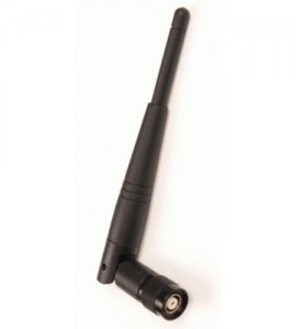
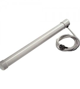

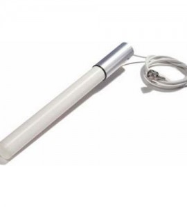


Cisco Aironet ANT1728
The antenna is used primarily with access points, but is compatible with Cisco Aironet radio products utilizing a reverse-polarity threaded Neil Concelman (RP-TNC) connector.
Designed for WLAN applications operating in the 2.4- to 2.5-GHz frequency range, the antenna has a nominal gain of 5.2 dBi. The antenna is used primarily with access points, but is compatible with Cisco Aironet radio products utilizing a reverse-polarity threaded Neil Concelman (RP-TNC) connector.
|
Antenna type |
Dipole |
|
Operating frequency range |
2.4- to 2.483-GHz |
|
VSWR |
Less than 2:1, 1.5:1 nominal |
|
Gain |
5.2 dBi |
|
Polarization |
Vertical |
|
E-Plane (3dB bandwidth) |
40 degrees |
|
H-Plane (3dB bandwidth) |
Omnidirectional |
|
Cable length and type |
3 ft (0.91 m) |
|
Dimensions (H x W) |
11.5 in. x 1.25 in. |
|
Weight |
4.6 oz (131 g) |

E-Plane Pattern
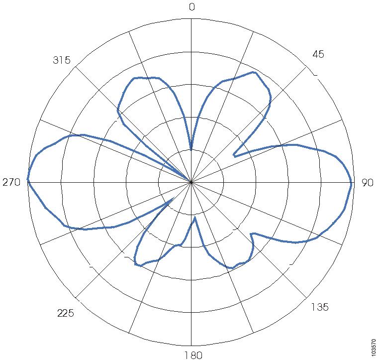
H-Plane Pattern

System Requirements
This antenna is designed for use with Cisco Aironet access points, but can be used with any 2.4-GHz Cisco Aironet radio device that utilizes a RP-TNC connector.
Installation Notes
Choosing a Mounting Location
The location of the antenna is important. Objects such as metal columns, walls, etc. will reduce efficiency. Best performance is achieved when transmit and receive antennas are mounted at the same height and in a direct line of sight with no obstructions. If this is not possible and reception is poor, you should try different mounting positions to optimize reception.
The antenna is designed to attach to and hang from a standard suspended ceiling track having a width from 13/16 inches (20.6 millimeters) to 1 1/4 inches (31.7 millimeters).
Tools and Equipment Required
To install the antenna on a suspended ceiling track, you will need the following tools and equipment.
•![]() A ceiling track bracket (shipped with your antenna)
A ceiling track bracket (shipped with your antenna)
•![]() A 7/16 inch (11.1 millimeters) wrench
A 7/16 inch (11.1 millimeters) wrench
•![]() Cable ties or electrical tape
Cable ties or electrical tape
The following sections contain procedures for installing the antenna to a suspended ceiling track.
Installing the Antenna
Follow these steps to install the antenna on a suspended ceiling track.
Step 1 ![]() Determine the location you wish to mount the antenna.
Determine the location you wish to mount the antenna.
Step 2 ![]() Loosen the hex nut on the ceiling track bracket.
Loosen the hex nut on the ceiling track bracket.
Step 3 ![]() Position the bracket on the ceiling track. See Figure 1.
Position the bracket on the ceiling track. See Figure 1.
Figure 1 Positioning the Ceiling Track Bracket

Step 4 ![]() Squeeze the bracket firmly onto the ceiling track.
Squeeze the bracket firmly onto the ceiling track.
Step 5 ![]() Use a 7/16 inch (11.1 millimeter) wrench to tighten the hex nut. Do not overtighten.
Use a 7/16 inch (11.1 millimeter) wrench to tighten the hex nut. Do not overtighten.
Step 6 ![]() Carefully screw the antenna onto the bracket`s threaded stud until it is hand tight. See Figure 2.
Carefully screw the antenna onto the bracket`s threaded stud until it is hand tight. See Figure 2.
Figure 2 Attaching the Antenna

Note ![]() If you use another mount, make sure the length of the threaded stud does not exceed 0.35 inch (0.9 centimeter).
If you use another mount, make sure the length of the threaded stud does not exceed 0.35 inch (0.9 centimeter).
Step 7 ![]() Use cable ties or electrical tape to secure the antenna coaxial cable along the ceiling track.
Use cable ties or electrical tape to secure the antenna coaxial cable along the ceiling track.
Suggested Cable
Cisco recommends a high-quality, low-loss cable for use with the antenna.
BENZER ÜRÜNLER
Diğer ürünlere de göz atabilirsiniz
Cisco Aironet ANT1728
The antenna is used primarily with access points, but is compatible with Cisco Aironet radio products utilizing a reverse-polarity threaded Neil Concelman (RP-TNC) connector.

Cisco ANT1728 Broşür